Tuesday, May 7, 2013

Panasonic FV-11VQ5 WhisperCeiling 110 CFM Ceiling Mounted Fan, White by Panasonic

Panasonic FV-11VQ5 WhisperCeiling 110 CFM Ceiling Mounted Fan, White

Have the Best Panasonic FV-11VQ5 WhisperCeiling 110 CFM Ceiling Mounted Fan, White For Your Needs

It can be that simple to consider a brand new Panasonic FV-11VQ5 WhisperCeiling 110 CFM Ceiling Mounted Fan, White and put it off as the next product which is the same as the many others out there, especially when there are various editions previously accessible. Not only does having a significant choice usually make it difficult for the consumer to select what type to purchase, it means that as a supplier we need to keep working harder to make a product which is much better than many of the rest of these out there.

Trying to keep this in mind, Panasonic has decided that we do not want to simply produce a different duplicate of the items that are already on the market. Rather that which we planned to carry out is present you with the perfect Panasonic FV-11VQ5 WhisperCeiling 110 CFM Ceiling Mounted Fan, White. Our company's research group researched the concepts previously being created then looked over everything you really wanted with this type of item before they even started design the very first layout. Their only goal was to provide you with a product which was unlike any you have ever seen.

We're excited to be capable to point out that what they invented will be the greatest Panasonic FV-11VQ5 WhisperCeiling 110 CFM Ceiling Mounted Fan, White currently available. We have built in all of the characteristics you have been hoping to see for decades and incorporated a number of our own extra individual variations we are sure you'll find cause our newest item definitely worth the exceedingly low price we are requesting for the item.

Panasonic FV-11VQ5 WhisperCeiling 110 CFM Ceiling Mounted Fan, White
List Price : $234.00

You Save : Check Lower Price

  Check Offer listing

Feature

  • Motor/Blower: Power rating of 120 volts and 60 Hz
  • Motor/Blower: Fan is UL listed for tub/shower enclosure when used with a GFCI branch circuit wiring
  • Can be run with no less than 110 CFM and no more than 0.3 sone
  • Housing: Double hanger bar system allows for ideal positioning
  • Grille: Attached directly to housing with torsion springs

Saturday, May 4, 2013

Solar Roof vent for Car, RV, Shed, Boat, Greenhouse by Unknown

Solar Roof vent for Car, RV, Shed, Boat, Greenhouse
You Save : Check Cheap Price

  Check Offer listing

Our Most up-to-date Solar Roof vent for Car, RV, Shed, Boat, Greenhouse Is Going to Make Your Life Even better

The moment you obtained your first Solar Roof vent for Car, RV, Shed, Boat, Greenhouse it is likely you thought that it was about to save you both time and expense, after all that was the whole factor behind the purchase of a item initially. While it is true that those early on models did make a difference and make your life easier, at Unknown we thought that it simply was not sufficient. You deserved a product which was not only likely to save you time, but was going to make your life far better.

Even though there are several alternative Solar Roof vent for Car, RV, Shed, Boat, Greenhouse currently available, we feel that what we did is taken the most effective components of a number of differerent items out there and used them to create our most recent version. Something that we did observe with so many of the various other merchandise on the market is that they try to impress you with very long lists of "exclusive" options they have included.

Our freshest Solar Roof vent for Car, RV, Shed, Boat, Greenhouse comes with its own set of functions, but rather than loading it up accompanied by number of pointless options, we dedicated to adding just those which our consumers let us know they preferred. We then concentrated on ensuring that every one of these functions functioned correctly, so that you might finally be able to pick the one product that was made with only one thing in mind and that to save no expense in making Your Life just that tiny bit better than it was.

Click here to see the Solar Roof vent for Car, RV, Shed, Boat, Greenhouse full review & cheap price

Solar Roof vent for Car, RV, Shed, Boat, Greenhouse

This solar ventilator removes hot humid air from roof spaces much more efficiantly than normal wind turbinesSimple instructions show you how to cut a 3 inch hole or drill a pattern of small holes in your structure. The solar vent comes with a mounting base plate for the outside and a vent grill plate for the insideSpecs:Voltage Voc: 2V Current Isc: upto 400mAInside grill size; 6x6Outside mounting plate; 6x6Fan unit; 5 1/2 in.Built in solar panel; 4 1/2 in.

Feature

  • Easily Mounts on Ceiling, Wall, House, Car, Boat, RV, Shed, Doghouse, Outhouse, You Name it!
  • No operating cost, charging by solar is free, safe, fast and easy
  • Helps to keep air fresh and removes odors from cooking, animals, etc Lets hot air out & cool air in
  • Circulates the air slowly and smoothly Weather resistant, and water resistant
  • Simple, easy to install, no wiring, no plugs, no electricity, no battery, no noise

Wednesday, May 1, 2013

Broan 671 Ceiling and Wall Mount Ventilation Fan by Broan

With pride Offer the most up-to-date Broan 671 Ceiling and Wall Mount Ventilation Fan

We're very pleased to tell you that we currently Offer up to date Broan 671 Ceiling and Wall Mount Ventilation Fan from Broan at drastically reduced costs. If you've been holding out to acquire one of them until the selling price was best, there has never been a more suitable time than today. After you look at the reduced price we are able to bring the product to you for, you will realize exactly how having the ability to acquire it only at that all-time low cost could make it among the best bargains you've come across in a very long time.

Broan 671 Ceiling and Wall Mount Ventilation Fan
List Price : $55.18

You Save : Check Price Now

  Check Offer listing

There are several models of this merchandise on the market; but there's just one manufactured by a really respected company name in the profession. There are many reasons why you need to get your latest Broan 671 Ceiling and Wall Mount Ventilation Fan from a brand name which you identify and depend on. To start with you're going to be getting merchandise manufactured by a business that you know you can trust since you probably already have exposure to a few of their goods.

The Broan 671 Ceiling and Wall Mount Ventilation Fan from Broan is not just yet another version of the same ones that are currently out there. the product has been remodeled from the beginning to offer you numerous new functions which will make it significantly more valuable than any of these products that you've used previously. Given the high demand and the fact that the product comes strongly recommended we're sure that you're going to be absolutely pleased.

Click here to read more about the Broan 671 Ceiling and Wall Mount Ventilation Fan full review & Low price

Broan 671 Ceiling and Wall Mount Ventilation Fan

The Broan 671 Bathroom Ventilation Fan features a durable 50-CFM blower wheel for consistent performance in any bathroom of your home. The fan operates at only 6.0 sones. Its compact polymer housing fits easily between ceiling joists or wall studs. Double-strength steel mounting flanges have keyhole slots for easy installation. Torsion spring grille mounting means that no tools are necessary. Housing Dimensions: 7.25L x 7.5W x 3.625H inches. Grille Dimensions: 9L x 9.25W inches.About Broan-NuTone Ventilation:Broan-NuTone has been leading the industry since 1932 in producing innovative ventilation products and built-in convenience products, all backed by superior customer service. Today, they're headquartered in Hartford, Wisconsin, employing more than 3200 people in eight countries. They've become North America's largest producer of residential ventilation products and the industry leader for range hoods, ventilation fans, and heater/fan/light combination units. They are proud that more than 80 percent of their products sold in the United States are designed and manufactured in the U.S., with U.S. and imported parts. Broan-NuTone is dedicated to providing revolutionary products to improve the indoor environment of your home, in ways that also help preserve the outdoor environment.

Feature

  • 70 CFM and 6.0-Sones
  • Powerful centrifugal blower wheel
  • Wall and ceiling mount
  • Compact housing fits easily between ceiling joists or wall studs
  • Backed by 1-year limited manufacturer's warranty

Tuesday, April 30, 2013

Industrial Gas Fired Ovens

CONSTRUCTION

A commercial Gas Fired Oven is usually of steel construction, composed of inner and outer shells of sheet steel sections, separated by 4" thick, 6 lb/ft3 density mineral made of woll insulation. The sections are built regarding minimize metal-to-metal contact between inner and outer shells and lower warmth flow from oven chamber towards the exterior surface. The structures are self-supporting, rigid, as well as sufficient strength to aid all auxiliary equipment. Interior surfaces can be created of 16 or 18 gauge aluminized steel and outer surfaces are constructed with 16 or 18 gauge aluminized steel too.

OVEN Writers &lifier Heating units

The Oven is heated by a number of gas fired writers. Writers are often situated within the combustion chamber, separated from work chamber. Typical burners capacity is 1. x 106 BTUH designed in a way the Oven shall achieve the right operating temperature in the required time. Electric heating units that might be used are situated around the walls from the Entry and Exit finishes from the Oven. Recirculation air within the Oven is heated by way of the gas fired writers within the combustion chambers and also the electric heating units around the walls. The style of the combustion chamber would be to fulfill the specs for gas fired heating.

RECIRCULATION SYSTEM

A Stove at roughly 25,000 CFM capacity for instance would discover one (1) Air Package Type Recirculation Fan with. The recirculation fan is finished with belt guard, belt drive, air flow switch, pillow block bearings, and secrets. The recirculation fans are impelled with a 5 - 50HP motor installed on a variable base.

EXHAUST SYSTEM

The Pre-heat Oven will get a number of General Purpose Exhaust Fans with 1,500 CFM capacity (each) normally. The exhaust fan is finished with belt guard, belt drive, air flow switch, pillow block bearings, and secrets. The exhaust fan is driven with a motor installed on a variable base.

SUPPLY AND RETURN PLENUMS

The Availability and Return Plenums are will include mister nozzles are constructed with 18 gauge aluminized steel which are adjustable to balance the flow. The new air is shipped within the Ovens in the supply plenum situated on the ground and it is came back with the top opening within the Combustion Chamber.

ELECTRICAL CONTROLS

One large NEMA-12 User Interface typically can be used to accommodate the controls. The panel could be connected to the Oven sidewall. A controller, switches, and showing lighting is mounted evidently from the User Interface. Additionally, the Oven has got the following controls integrated into the machine:

o Control Energy Selector switch.

o High Temperature Limit to make sure hot temperature safety.

o Temperature Controller to manage burners.

o Combustion Air Blower is integrated towards the burners like a warmth source as well as for complete combustion from the fuel gas.

o Fan Interlock: All fans are interlocked by air flow switches to avoid getting too hot from the Oven if fan is either off or inoperative.

o Power supply

Sunday, April 28, 2013

Centrifugal Roof Mounted Exhaust Fan DB24VH1S by Soler & Palau USA

Centrifugal Roof Mounted Exhaust Fan DB24VH1S
List Price : $1,322.00

You Save : Check Price Now

  Check Offer listing

You're thrilled by the Centrifugal Roof Mounted Exhaust Fan DB24VH1S, new item from Soler & Palau USA which out within the market now. Our no limits capture and try to utilize some various technologies to really make it real for everybody. Some of the investigation that we put in this item came from the consumer relative encounter along with the length expertise. That is a compelling item that make Soler & Palau USA is much more success and well know within the market about the globe.

This new item thought that we try to came across to produce a wonderful item for consumer about the globe came from our consumer data and wonderful inclusion modern expertise. Centrifugal Roof Mounted Exhaust Fan DB24VH1S is going to be in each family that searching for a far better lifestyle. In each process away from the intelligent manufacturing and intensive product's good quality manage lead us on the confident that we'll be capable of give our consumer the perfect answer that they've been searching for. Simultaneously as deciding on household development and private item is especially essential for you. We've developed our productive the Centrifugal Roof Mounted Exhaust Fan DB24VH1S from our extensive circumstances encounter inside the company.

From this moment on you can really uncover That is definitely not too difficult for you and your loved ones to have a fundamentally comfy life style and take pleasure in your time by spending tiny of one's spending spending budget.

Click here for information Centrifugal Roof Mounted Exhaust Fan DB24VH1S full review & cheap price

Centrifugal Roof Mounted Exhaust Fan DB24VH1S

24" DownBlast Belt Fan 2hp 120v 1ph 900 rpm

Feature

  • 24" DownBlast Belt Fan 2hp 120v 1ph 900 rpm

Thursday, April 25, 2013

Growth of the brand new You are able to City Subway System

Brooklyn Rapid Transit and the Dual System:

By all accounts, the IRT had achieved success-and monopoly-carrying 269 million passengers in 1910. Clearly, the demand existed, but the distance did not. Compared to the 66.1 route miles of elevated track, its own covered only 21.4, along with a paltry 3.8 more under the contract #2 extension to Brooklyn.

More than transportation, the subway was seen as a tool--a solution toward population redistribution, particularly to the outer boroughs. But this minuscule Brooklyn line could hardly achieve that goal, and the initial two contracts were only considered the first of many that would eventually cover mostly farmland with tracks.

Although the Rapid Transit Board (RTB) approved 19 succeeding routes by June of 1905 in hopes of creating competition between the companies that would operate them, future direction of the subway system, in more ways than one, was delayed, deferred, or derailed by obstructing and conflicting policies, as the pendulum swung in the opposite direction, toward further IRT monopoly, when it announced its acquisition of the Metropolitan Street Railway Company on December 22. Tightening its grip on the city's rapid transportation system, it had no intention of relinquishing it to competing companies nor expanding the routes it already operated.

Perhaps the first counter-strategy to this situation was the creation, two years later, of the New York State Public Service Commission (PSC). Unlike the Rapid Transit Board it replaced, it was empowered with the ability to oversee all existing elevated and subway lines, and advocated public regulation of private utilities.

Although it was eager to negotiate with the IRT regarding the extension of its incubation line in Brooklyn, it also identified the need for a second company to provide the needed transportation coverage over and above that of the first. But the IRT only continued to hold a short-term, self-centered view. Astronomical construction costs of new routes, it felt, could not be compensated by the dearth of riders they would serve in areas still populated by farm animals, and this only resisted expansion beyond its original Manhattan coverage. Its passenger base here had doubled in the five-year period from 1905 to 1910, and its profits commensurately followed suit.

Like Manhattan, Brooklyn had been blanketed by a disjointed, multiple-mode transportation network comprised of trolleys and both street and elevated railroads pieced together under the auspices of the Brooklyn Rapid Transit Company. But its link to mother Manhattan was tenuous and less than convenient.

Traveling to it entailed a cable car ride from the Sands Street terminal, located at the foot of the Brooklyn Bridge, actual crossing of it to City Hall, and then a separate-fare transfer to one of three inter-city rail options-the Second Avenue el, the Third Avenue el, or the IRT subway. Alternatively, a person could cross the bridge to the Park Row terminal via elevated railway.

What were needed were both a cross-river, Manhattan-Brooklyn link and an inter-Brooklyn subway network. Because of the IRT's resounding success, it logically followed that it would extend its tracks.

Outer borough links, at least based upon the many civic projects undertaken, provided no obstacles. The Brooklyn Bridge, for example, had already spanned to its namesaked destination in 1883, and the Williamsburg and Manhattan bridges, built during the first decade of the 20thcentury, further connected the two areas. The Queensborough Bridge, as its name suggests, served the same purpose for its territory. What remained was the laying of tracks on them.

August Belmont, naturally seeking to retain the IRT's grip on the rapid transit market, proposed connecting South Ferry in Manhattan with Atlantic Terminal in Brooklyn by means of an East River tunnel, as well as expanding inter-Manhattan trackage on the Lower West Side and laying a Lexington Avenue line from Grand Central Station.

Yet its proposals were less than extensive. All were sections, add-ons, or piecemeal extensions of its existing lines and none of them provided the fundamental coverage the PSC considered unwritten obligations resulting from its Contract #2 award.

The Hudson and Manhattan Railway Company suggested a New Jersey connection by building a new, Hudson River tube-plying subway line.

A second, and countering, proposal submitted by Belmont advocated a new West Side route running from Times Square to the Battery and then crossing the East River to Brooklyn, as well as a second course from Grand Central Station to the Bronx by means of Lexington Avenue.

It was apparent that the IRT did not consider Brooklyn its home territory and wanted little part in serving it. This view may well have been the first fray in its independent and monopolistic rail fabric.

Part of the fray was its refusal to see the purpose it provided-or could have provided-within the overall rapid transit picture. Having already implemented a plan to relieve population congestion in the tenement-choked slums riddled with crime, disease, poverty, squalor, and dirt with planned development, Manhattan Borough President George McAneny believed its cornerstone was elevated and subterranean rail access to new neighborhoods, which, appendaged to Manhattan by tracks, would naturally rise, sparking the envisioned outer borough growth. This, in turn, was seen as fostering overall economic strength.

The IRT, because of what it refused to see (beyond its own self-serving needs and revenues), could no longer be considered the only company to fulfill the city's plan, and proposals for the so-called, but far more extensive Triborough System, also failed to satisfy it. What resulted was the Dual System of Rapid Transit.

Threshold to this concept was the January 19, 1911 creation of a new transit committee, which was chaired by McAneny himself and conferred with the PSC for the purpose of re-examining New York's rapid transit needs.

Part of the solution was to discontinue the focus and fixation on the principle proposals concerning IRT track extension and the new Triborough System coverage as the only ones. The latter, particularly, was quickly deemed impractical. The solution was a third alternative, to be operated by the Brooklyn Rapid Transit Company (BRT), which already served its namesaked borough and submitted a proposal to convert its southern rail lines into rapid transit ones.

Although this fell far short of the comprehensive coverage needed, one of the locks to the optimal solution was opened when it was concluded that the subway systems themselves, often acting in their own best interests, would henceforth no longer be empowered with determining future routes.

McAneny himself stated that he "always held that the city should make its own transit plans, placing individual routes where they will do the most good and not necessarily with reference to their earning capacity alone... "

In order to develop what he considered would be a practical, yet comprehensive rapid transit system that would deliver the maximum benefit to the city and its citizens, he selected the best features of both the IRT and the BRT proposals based upon routings, cost, population projections, ridership, and revenues, allowing both to proportionately operate-and share the costs for--the expanded system

The resultant Dual System of Rapid Transit constituted the largest and most expensive municipal project ever undertaken by the city, its routes and tracks planned and laid out by PSC engineers, but its actual construction performed by private companies.

Two general route types were expected: extensions and branches of existing tracks, which would be operated by the IRT, and new lines, which would be served by a new company, such as the BRT, but would still be integrated with the original ones.

Dual system approval, by a vote of three to two, was granted by the PSC on March 4, 1913, and the signing of two-or dual-contracts, stipulating that each would share construction and operation costs, but lease their networks to the city for a 49-year period, occurred 15 days later, on March 19.

Contract #3, awarded to the IRT, entailed ten new routes in Manhattan,, the Bronx, Queens, and Brooklyn that opened between July 1, 1918 and January 21, 1928.

The new system's greatest improvement was the gap it plugged in its original north-south, inter-Manhattan, zigzag route coverage. West Side track laid south of 42ndStreet ran under Seventh Avenue to Lower Manhattan and then across the East River to Brooklyn, while an East Side counterpart, running below Lexington Avenue, extended north of 42ndStreet, creating an "H" configured network, which became the core for feeder lines to and from the Bronx and Brooklyn.

Service to the former was expansive, but decidedly less so in the latter, since it had to cede routes to home turf competitor BRT, although a Flatbush Avenue routing, itself an extension of its existing track, terminated in Eastern Parkway and branch lines from Nostrand Avenue took its trains to East New York. All these lines fed its trunk, H-shaped Manhattan network.

A Queens connection, facilitated by the converted Steinway Tunnel, linked 42ndStreet with a new transfer station at Queensborough Plaza from which two lines ran-one to Astoria and the other to Corona and Flushing.

Unlike the Manhattan track, most serving the outer boroughs was elevated.

Contract #4, between the PSC and the New York Municipal Railway Corporation (for the BRT), entailed 12 routes opened between August 4, 1913 and May 30, 1931, and enabled it to leave a significant imprint on Manhattan Island.

Running from City Hall, via Broadway, to Times Square, and then following Seventh Avenue to 57thStreet, this trunk line was appendaged to its Brooklyn home by means of the Battery and an East River tunnel that took it to Dekalb Avenue. A second connection from the Broadway line entailed a branch track to Canal Street and across the Manhattan Bridge, once again terminating on Dekalb.

Another Broadway line branch connected 59thand 60thstreets with Queensborough Plaza, and IRT track rights enabled the BRT to ply its rails to Astoria and Corona/Flushing.

It wove a dense web of tracks across southern Brooklyn with the Fourth Avenue, Culver, West End, Sea Beach, and Brighton lines--Dekalb Avenue all along serving as the funneling point for interline transfers to and from Manhattan.

Expansions and improvements undertaken as a result of both the IRT Contract #3 and BRT Contract #4 arrangements also entailed the elevated railways.

Advantages of a dual-contract subway system were considered two-fold: 1). Passenger interchange would be provided between two significant rapid transit networks and 2). Vitally needed rail coverage to and within the BRT's home territory, which had either been devoid of tracks or inefficiently and disjointedly served by its existing ones and their now-antiquated transportation vehicles.

But a dual-contract system quickly proved that it was not equitable with "double" the previous single one, much less compatible. Indeed, "dual," in this case, was more akin to "duality"-translated as "competitive rivalry." Fares were separate. And there were precious few connections, interchanges, or even pedestrian passageways between their stations.

More importantly, the two systems were, from the outset, divergent. Although their track gauges were identical, the BRT was not hampered by the narrower tunnels, lower clearances, and sharper curves characteristic of the IRT system that had mandated specific car dimensions and train lengths. Unburdened by these restrictions, the BRT was therefore free to specify different car designs and rolling stock interchange between the two, aside from all the other rivaling aspects, was precluded.

Manufactured, like the IRT cars, by the American Car and Foundry Company, and retaining the features for which no patent payments were required, the BRT counterpart deviated in dimensions, with a 67-foot length and 9.8-foot width, and introduced steel body construction from the outset. Accommodating 250 standing and seated passengers, the latter in both longitudinal and transverse, mid-cad car seats in a three-two configuration, the 47-ton coach, powered by a 140-hp motor on each of two trucks, was accessed by three sets of electro-pneumatically operated doors and was internally unobstructed except for the motorman's cab. They were devoid of end vestibules.

Designated "A-Bs" or "Standards," they were initially underpowered and therefore only able to attain 39-mph speeds.

Deliveries of the first 100 ordered began in 1914 and 400 more followed during the proceeding four years.

As had occurred with the IRT system, the BRT experienced unprecedented demand and one of the remedies was to introduce articulated, tri-car units, in 1925.

Manufactured by the Pressed Steel Company and designated "D" cars, the three semi-permanently coupled coaches were equipped with four 200-hp motors and were mounted on four trucks that were "shared" by the middle car.

Seating was similar to that of the "A-Bs," but the transverse arrangement called for two passengers on either side.

A three-car unit equaled the length of two conventional coaches, but offered greatly increased passenger capacity.

After their initial trials had proven their application, 118 more units were ordered.

In essence, dual-contract operations resulted in the following coverages. The IRT served Lexington Avenue above 42ndStreet; Seventh Avenue and Broadway below 42ndStreet; the 42ndStreet Shuttle; all lines north of 60thStreet in Manhattan and the Bronx, including those that were elevated; and the Second Avenue tunnel to Brooklyn, whose dual branches terminated on Flatbush Avenue and in East New York. The BRT, on the other hand, operated the Fourth Avenue subway; the Manhattan Bridge and the Montague Tunnel; the Broadway-60thStreet subway; the Nassau Street Loop and the 14thStreet Canarsie line; and the reconstructed and extended elevated lines in North Brooklyn and Queens. The Steinway Tunnel to Queens, Astoria, and Corona were jointly operated by both systems.

Unlike the original IRT subway routes created by contracts 1 and 2, the dual system succeeded in sparking outer borough growth and transformed vegetation into population.

With the strangely predictive designation of "Trains Meadow," for instance, a 500-acre tract of land in north-central Queens between Woodside and Corona became the recipient of one of those transformations. Although its meadow reference was appropriate to this bucolic expanse of grass- and flower-covered fields and knolls interspersed with ponds and streams and dotted with farmhouses, it was not named after the trains that served it, but the fresh water that drained from it, although those trains would one day provide more literal meaning to the word.

With a turn of the 20thcentury, count-on-one-hand population density of two per acre, it served as a country escape for city dwellers, offering bird-watching, fishing, and hunting, but with the encroaching, track-clacking subway cars, it soon turned into a breeding ground more appropriate for humans than waterfowl.

After the Steinway Tunnel had been converted from its original, electric streetcar application and reopened on June 22, 1915 for IRT use, it provided the physical link to Manhattan rising on the horizon. People, needless to say, rode the trains that bored through it.

Subway-appendaged, via the 82ndStreet station when the Queensborough line opened two years later, on April 21, it became a 22-minute link to Grand Central Station, and was developed by Edward Archibald MacDougall, who renamed it Jackson Heights and built a garden apartment community for upper middle class residents. Caught by the city's clutches during the day, they were able to escape to its suburbs by night.

Cord Meyer, another developer, transformed the southern portion of Trains Meadow into Elmhurst.

Accessing areas like this, the greatly expanded rapid transit system turned the patchwork quilt of farms sprouting crops into grids defining houses and low-rise apartment buildings, which cultivated families and neighborhoods and served them with stores, schools, and sites of religious worship. They were considered "subway suburbs." Tracks, facilitating daily commutes, were links to the heart of the city, with its employment, entertainment, and cultural venues.

Their purpose was reflected by the exponentially increasing passenger statistics. In 1912, for example, the IRT transported almost 303 million. In 1930, this figure had escalated to 986 million. The corresponding BRT figures were 172 and 714 million.

As a people mover, the expanded system provided short-term (daily) and long-term (residency shifting) effects between 1910 and 1940, resulting in a 90-percent population increase in the so-called subway suburbs, created by the very means to get to them.

And once they had, their quality of life considerably improved. Compared to the tenement-defined slums from which families often moved, they provided larger and more modern dwellings in the suburbs for the same cost, yet with vastly improved facilities, such as rooms with windows, ventilation, and natural light; heat; running water; private, indoor bathrooms and kitchens; courtyards; and gardens.

In short, subway mobility created social mobility, depositing people into population pockets that were considered middle class.

Despite the dual subway system's less than cooperative nature, it was successful in connecting Manhattan Island, like a nucleic core, with the rest of its atom, traversing the rivers that had hitherto created its insularity. As the world's largest single subway network expansion, it entailed a route mileage increase from 119 to 233 miles with corresponding track mile increases of 296 and 621. Although there were several elements which divided it, collectively it united-albeit not itself, at least not yet.

The only question that remained was: could there be a third system?

The Independent:

Dual-contract service, at least initially, was successful and all counts associated with it were on the rise, from the number of areas accessed to the number of stations, riders, and track and route miles. As a catalyst to population redistribution and decentralization, it provided incentive toward and accesses to outer borough development.

But such an extensive system required, more than rails, revenue to run, and the nickel fare, restricted by the 1894 Rapid Transit Act, Contract #1, and ultimate dual contracts of 1913, was the one reversal to the rising aspect of the new operational concept. Because the very nature of the subway precluded the traditional revenue-to-distance ratio, passengers were able to ride further afield on the now extended network, yet did not commensurately pay for that privilege. Whether a person rode the subterranean rails to the next station or to the end of the line, he still only relinquished five cents, reducing, rather than increasing, the system's revenue earning potential.

Its balance statement, appearing more like a seesaw, was anything but, its profit side declining into deficits and its costs escalating toward the skyscrapers above its track.

One of its two contract operators hardly emerged unscathed. A December 31, 1918 bankruptcy of the Brooklyn Rapid Transit Company questioned its continued viability until it re-emerged as the renamed Brooklyn-Manhattan Rapid Transit Company, or BMT, five years later, in 1923.

To say that John F. Hylan, New York mayor, was less than enamored by the system run as much by politics as by electricity was an understatement, and in his 30-page "Mayor Hylan's Plan for Real Rapid Transit" report, he wrote that subways should be "planned, built, and operated to accommodate the transportation needs of the people... and not solely for the financial advantage of the operating companies."

His vision, in essence, was to wage a war on wheels-or, more specifically, on rails-fought with a third specifically-designed and efficiently and independently operated system that would compete with the existing and monopolistic IRT and BMT, often paralleling their very enemy lines, but also filling in trackless gaps. It was intended, in his words, as "the people's subway."

The tunnel toward his ideal came in the form of the Adler Bill. Although it ensured the New York State Transit Commission's power to regulate the existing subway system, it equally established the New York City Board of Transportation, which was granted the authority to construct and operate its own subway network, as well as grant desperately needed fare increases, after a three-year period, to cover escalating operating costs.

The new, or third, subway line's nature was expressed by its very name-"Independent"-or "IND." It had, at least according to combatant Hylan, four intended purposes.

1). Compete with, but remain independent of, the incumbent IRT and BMT systems.

2). Replace the antiquated elevated lines in Manhattan and the Bronx.

3). Serve areas without existing train service, such as those along Queens Boulevard.

4). Increase service to areas with inadequate transportation, such as Washington Heights and West Bronx.

Seven fundamental routes were covered with 190 miles of track. For Hylan, duplication of competitors' lines was the equivalent of retaliation and triumph. The IND's Eighth Avenue route, for instance, was a mirror image of the IRT's on the Seventh, although its reflection ceased at 59thStreet and Columbus Circle, where its tracks branched. One turned to the west, toward the Hudson River, and the other followed the Grand Concourse in the Bronx after crossing the Harlem River.

Where the tracks paralleled the IRT's-separated by an avenue-the IND vied for the same passengers. Perhaps the ultimate expression of audacity was made with its Sixth Avenue line: it operated directly below the elevated railway owned by the IRT!

Route battles, however, were not restricted to those with Manhattan's original system. The BMT also became a sparing partner when the IND laid tracks to Brooklyn through an East River tunnel, advancing its fortress along Fulton Street in the heart of the city and ceasing battle in East New York.

As a competitor, the IND, from its inception, sought to offer superior service, with mezzanine provisioned stations, 60-foot platforms, and ten-car trains.

The cars themselves, although dimensionally compatible to the BMT's "A-B" types, eliminated certain features in order to avoid the otherwise mandatory royalty payments for them stipulated by their patents.

Designed "R-1s" and built by the American Car and Foundry Company, the riveted, heavyweight steel coaches were powered by two 190-hp traction motors installed on the number two truck and were 60 feet long, ten feet wide, and 12 feet high-or nine feet longer than those of the IRT, but seven feet shorter than those of the BMT. Access was provided by four, 3.10-foot-wide double doors (one more than those initially installed on BMT cars), while end doors facilitated inter-car passage during motion.

The olive green interior, in a mixed, longitudinal and transverse configuration sported rattan- or cane-covered seats and accommodated 58 seated and 282 standing, while other features included exposed light bulbs, paddle fans, strap handles, and a clerestory roof.

Compared to those operated by the BMT, they offered increased speeds.

The first section of the Independent system opened on September 10, 1932.

Unification:

As the third subway system went up (actually down), the elevated railroads it replaced fell like conquered, grid iron empires, the girders and stanchions that had stilted them severed and the sun, after decades, once again able to cast its light on the streets that had been shielded.

The Fulton Street el in Brooklyn absorbed its last track clack in 1940. The Second and Ninth Avenue lines followed suit, reduced to defeated tangles of metal. And the famed Third Avenue el, subjected to much protest by those wishing to save it, relinquished its grip in 1955.

Some two decades before this time, however, the rival to the other two subterranean rail networks had accepted defeat and become one with the other two.

The impetus came from Fiorello La Guardia, who was elected New York mayor in 1934. Advocating unification of the three subway lines, he felt that the city would be more efficiently served, but many believed that his true motivation for the amalgamation could be read between those lines.

His urge to merge, which was intended to drastically amend the system's organization, ownership, and operation, manifested itself in a 1935 agreement in which the City of New York would expend a little over 0 million to acquire the IRT, the BMT, the Williamsburg powerplant, and what then remained of the elevated lines, and then lease them, along with the IND, to the Board of Transit Control to operate them.

But the Transit Commission saw both his plan and the shadow behind it. It believed that it would have enabled La Guardia to provide sorely needed bail out funding to a subway system unable to remain afloat by the current nickel fare restriction at an excessive acquisition price, thus forcibly ceding ownership of it, in the end, to the bankers.

Undaunted, La Guardia circumvented the resistance. Re-elected in 1937 and eliminating most of the Democratic Tammany opposition within the Transit Commission, he was able to implement his idealized plan, in effect acquiring more for less. The package included the two subway systems, the elevated lines, the street railways, and the buses for 6.5 million, an amount that represented more than a 0 million savings over the original proposal.

Unified in June of 1940, this multiple-mode rapid transit system thus shifted into City of New York ownership and the Board of Transportation became its operator. Passed from private to public hands in what was heralded as the country's largest railroad merger, it became the world's largest rapid transit system, its hitherto three IRT, BMT, and IND designations discontinued and redesignated "A" and "B" divisions. The latter, referring to the BMT and IND, was subdivided into B1 and B2 divisions.

Only its truly staggering statistics could define the size and scope of the resulting empire: 760 miles of subway and elevated railway tracks, 435 miles of street railroads, 80 miles of bus lines, and 2.3 billion passengers carried during its first full unified year alone.

Sunday, April 21, 2013

Some Good Good reasons to Choose a Bard Ac

Bard air conditioning units are produced and promoted by Bard Manufacturing since 1914. In excess of 90 years, the corporation provides the best quality of air conditioning units which are a mix of high quality and technological advances.

These models are made to deliver reliable and efficient cooling solutions. These include a number of patented features like control modules and ventilation options. The business is renowned for its diverse selection of attached to the wall models for multiple reasons varying from schools, hospitals, houses and commercial institutions. The organization has exercised the needs of every single sector at length and it has been supplying items to match individuals needs whenever possible.

The primary causes of selecting Bard Air Conditioning Units are the following:

· Installation - These don't require any transmission on the top and therefore are therefore simple and easy , affordable to set up.
· Inexpensive - Because these models aren't placed on the top, a ten SEER unit works in addition to a 13 SEER unit that's placed on the top. This guarantees the clients obtain a huge saving the moment they install one of these simple models as lower SEER models are comparatively less costly to buy.
· Space saving design - These models are installed on the walls and therefore increase the space available within the room. This can help to get the utmost from home or office.
· Complete control - These models could be controlled to this kind of extent the temperature in every individual room could be set as preferred. This removes the issues developing because of choosing only one particular temperature setting for the whole house, office or school.
· Options provided - These supply the choice to the clients to choose either the ducted or even the non ducted variety according to their requirement.
· Durable - These include a pre colored steel cabinet that's durable enough to last a long time without rusting even if it is available in connection with the sun and rain of character.
· Total protection - The interior product is protected against damage by a sophisticated organs and circulatory system control protection that can help prolong its existence.
· Unique combinations - A few of the models available possess the capacity to mix electric ac with heating by gas. This will make them very reasonable to function.
· Other features - These models include an in built rain hood to safeguard the models placed on view from direct rain water. Forms of fitted rich in pressure control, wall mounts and outdoors damper.

These models provide a lot in a competitive cost that it's an very wise proceed to choose on them other models. During a period of time a lot of educational facilities and office have installed these energy-efficient models.

Saturday, April 20, 2013

Quiet Vacuums: The Number Of Sound levels? Purchasing Tips

Cleaning and cleaning in your house might be a much irritation, if perhaps your vacuum wasn't so noisy and irritating. You'd most likely have the ability to hear the doorbell or telephone ring should you have had a quieter vacuum. In addition, the noisy noise from cleaning in your house wouldn't distress everybody, which includes your felines or dogs. Buying a top quality quiet vacuum is one thing that needs to be surface of your grocery list. Family people could be less reluctant to obtain the vacuum out, and you'll end up residing in a cleaner fresher atmosphere. There'd be pointless to help keep stalling the cleaning for an additional couple of days. The health advantages of standard cleaning in your house really enhances your indoor quality of air for everybody under that roof.

Surveys in last couple of years through the large electrical and vacuum producers, discovered that most customers wanted they'd thought more to do with our prime noise volumes their own vacuums made before purchasing them. Consumer surveys also revealed that because of the option, most purchasers would choose a less more noisy vacuum, even when it had been more costly than their previous vacuum.

Contributing to this, additionally, it came to the conclusion that many people also strongly connected quiet vacuums rich in quality items, much more reliability, better cleaning efficiency and gentler towards the atmosphere generally. Because of advanced vacuum engineering technology, you will find plenty of very good quality quiet motor vacuums on purchase that aren't too costly, offer good suction and also have excellent overall cleaning performance without individuals annoying noisy motor sounds, that may make your wheels spin.

Importantly, a lot of us want to understand how quiet is really a quiet vacuum? Conventional vacuums possess a motor noise creation of roughly 74-81 Decibel's. This isn't acceptable for any vacuum in your house to command and pollute your house atmosphere to this kind of extent because more recent vacuums models tend to be quieter than this unhealthy noise output.

Generally you will notice that canister vacuums and quieter upright vacuums might operate around 72 dB. However this decibel range is 'exponential', because this volume decrease implies that the audible noise amounts of modern quiet vacuums available on the market happen to be reduced by 50%. They emit a minimal whistling kind of noise, that is very comfortable to reside with and far quieter than previous noisy vacuums.

Getting large noisy motors set up in your vacuums aren't needed within this modern era, because technological enhancements within the vacuum engineering industry will always be finding better techniques to produce a better customer experience, which does connect with enhancing features for example suction ability with no demand to set up greater wattage motors in vacuums.

Keeping vacuum performance high could be carried out by creating specialist tapered fans, which function by improving the environment suction energy without resorting to a 2000 + W vacuum motor. Lesser Wattage, quiet vacuums might have greater suction energy than other vacuums with effective motors installed, but still keep your decibel level in a low and comfy cleaning range.

Having a basic vacuum means you are able to vacuum and clean your house if you spare the time, and without disturbing other family people in your house. Maybe cleaning while some are reading through a magazine or watching tv may be going too much. Not such a long time ago, vacuum sales people were misleading potential clients into thinking that purchasing a higher wattage vacuum/motor would offer you better dust/debris suction energy, which obviously is nonsense. Modern high-tech 'quiet' vacuums today use less energy but nonetheless offer you high suction.

The most quiet vacuums use varied strategies to reduce machine noise levels, beginning with creating the turbine inside a manner to lower high-pitched noise emission. This noise is very irritating and frequently created by motor parts spinning at a lot more than 30,000 revolutions each minute. Vacuum motors within the most quiet vacuums are installed on noise-conditioning brackets, and enclosed in seem-muffling substance.

The vacuums 'Air Flow' is really a main factor in identifying the most quiet vacuums. Vacuum engineers plan to reduce air turbulence at two important places, the motor air inlet, as well as the vacuum air exhaust. However in general, the motor's air inlet within the dust bag container is big, and it has an aerodynamically funnel shape structure. Reducing air turbulence reduces noise levels out of your machine.

Cylinder vacuums are mainly quieter than uprights, however the noise levels between different canister models and vacuum producers vary quite a bit. Before purchasing any vacuum machine, it's worth asking a couple of questions first. It's inside your interest to discover concerning the vacuum motor energy, as it doesn't need to have high wattage energy to possess high suction ability, and low w means less decibel's or noise level.

So far as the atmosphere is worried, environmental noise is one thing that's mostly overlooked in present day society, but it may cause hearing difficulties for everybody, not only the seniors. You should know of the fact, particularly if you have noisy machine functioning in your house. Noisy noise from neighbours, cars, lorries, noisy music, jet planes, noisy vacuums, ac models, televisions, dish washers, automatic washers along with other high decibel home home appliances can impact your wellbeing and could cause early hearing difficulties.

Considering buying a basic vacuum? Then you should be striving in a canister vacuum which will output under 70 decibel's. You have to understand that upright vacuums is a couple of decibel's more noisy than canister or cylinder vacuums, but fortunately there is indeed a very wide array of quiet vacuums to select from on the web and in shops. Greatest recommendations visit Sebo and Miele, simply because they manufacture only the greatest quality quiet vacuums, which do provide excellent performance. Carrying out a little homework on quiet vacuums first can help inside your final purchasing decision, so you've a quieter atmosphere in your own home.

Thursday, April 18, 2013

Panasonic FV-40VQ4 WhisperCeiling 380 CFM Ceiling Mounted Fan from Panasonic

Panasonic FV-40VQ4 WhisperCeiling 380 CFM Ceiling Mounted Fan

Are In Possession Of the newest Panasonic FV-40VQ4 WhisperCeiling 380 CFM Ceiling Mounted Fan Available For You

How frequently have you purchased a completely new Panasonic FV-40VQ4 WhisperCeiling 380 CFM Ceiling Mounted Fan only to find out that it won't have all of the features you probably expected it possess or perhaps that for one reason or any other, it simply does not perform the way you expected it to? Well for those who have then you are about to really really like the most recent design from Panasonicas we assure you won't ever be unhappy with its efficiency.

We all also be aware that while exactly how well our brand new Panasonic FV-40VQ4 WhisperCeiling 380 CFM Ceiling Mounted Fan performs is essential for you, it is not the only reason you might consider updating the one that you already have. Typically in regards to this sort of product you are equally as focused on the built-in characteristics that it comes with. This is when you will find that our brand-new product far outshines the the competition in a big way.

We've gone to great measures to ensure that we heard what you actually want to see in a Panasonic FV-40VQ4 WhisperCeiling 380 CFM Ceiling Mounted Fan prior to developing our edition. our most recent brand includes as many of those capabilities as we could probably construct in it. When you're prepared to purchase a cool product like this, you'd like to learn that your money is going to be spent well. We are sure when you realize all the things our brand-new product is able to do, you will agree that it's well worth the everyday cheap price We are marketing it for.

Panasonic FV-40VQ4 WhisperCeiling 380 CFM Ceiling Mounted Fan
List Price : $494.00

You Save : Check Cheap Price

  Check Offer listing

Get a noise-free, easy-to-operate fan in the form of the Panasonic WhisperCeiling FV-40VQ3 Ceiling Mount Bathroom Fan - ENERGY STAR. Configured with high-quality components and a condenser motor, this fan is high on the CFM-to-watt efficiency. The built-in damper which prevents backdraft keeps the environment at a stable temperature. The uncomplicated wiring and the inclusion of detachable adaptors and adjustable mounting brackets make for easy installation.

Feature

  • Totally enclosed condenser motor and double-tapered, dolphin shaped bladed blower wheel quietly moves air
  • Quiet enough that you might not even know it's on
  • Continuous, trouble-free operation for many years due to high-quality components and permanently lubricated motors
  • Fan housing is made of heavy-gauge zinc galvanized steel
  • Rated 380 cubic feet per minute

Monday, April 15, 2013

The Boeing 757

I

Increasing demand on existing Boeing 727 routes, which often eclipsed the capacity of even the stretched, -200 series version, coupled with advanced technology, dictated the need for either a larger variant of this venerable tri-jet or an altogether new design.

The first attempt, adopting the former approach, had featured a fuselage sufficiently stretched to accommodate 189 passengers and three refanned, higher-capacity Pratt and Whitney JT8D-217 engines, each developing 20,000 pounds of thrust. Designated the 727-300B, it first appeared at the 1975 Paris Air Show in model form. Despite initial interest from United Airlines, carriers had felt that it needed quieter, still-more advanced powerplants.

A fundamental redesign, retaining the 727's nose, forward fuselage, and t-tail, and designated "7N7," featured a further fuselage stretch and a new technology wing, mated, like the much smaller 737, to two pylon-mounted engines, of which the Pratt and Whitney JT10D-4, Rolls Royce RB.211-535, and General Electric CF6-32 had then been considered. Although it had been intended, like its inceptional counterpart, for one-stop transcontinental sectors, its wing contained sufficient fuel tank volume for eventual, long-range deployment.

Because widebody comfort had been well received by passengers on intercontinental routes, one iteration had briefly explored a wider fuselage cross section for twin-aisle, 180-passenger accommodation. The concept would have satisfied two needs: 1). It would have offered increased comfort, and therefore been more competitive with the then-pending Airbus Industrie A-300 on relatively short US domestic sectors, and 2). It would have avoided the excessively long fuselage needed to cater to any future capacity increases, obviating the requirement for long undercarriage struts to maintain proper take off rotation angles.
The envisioned width, however, had been too much of a payoff for these advantages, as evidenced by weak airline interest, since the weight and drag associated with a second aisle and only one more seat abreast had been impractical, and its cross-section, although wider than that of the 7N7, had still been too narrow to accept standard LD-3 baggage and cargo containers.

Reverting to its narrow body studies, Boeing proposed an advanced, large-capacity 727 which, by February of 1978, had featured its nose, cockpit, and fuselage cross-section, but had introduced a new wing and two turbofans for a 170-passenger complement, thus employing much of the commonality of the simultaneously-developed, twin-aisle 7X7 design. Redesignated "757," it would be Boeing's fifth major commercial jetliner to carry the seven-dash-seven model sequencing numbers, after the 707, 727, 737, and 747, all but the last of which had been narrow bodies.

Compared to the 727 it had been intended to replace, it had offered a 15-percent lower fuel consumption, yet its significant wing area inherently fostered weight, range, and capacity increases for any future derivatives.

In order to reduce development costs associated with its 767, the widebody, twin-aisle, twin-engined counterpart initially also intended for one-stop transcontinental routes, Boeing, where feasible, incorporated maximum commonality in the two aircraft and the types therefore shared the same forward nose sections, windscreens, quad-wheeled main undercarriage units, avionics, and flight deck systems. Indeed, the two aircraft, forming a new-generation of advanced narrow and widebody twinjets, would offer a common type rating, augmenting mixed-fleet flying of carriers which operated both types, and even the originally intended, 727-style t-tail had been deleted in favor of the conventional 767, low-wing configuration at the very end of the design phase, resulting in greater commonality with the 767 than the 727 it was intended to replace.

Launch orders, for 21 firm and 24 options and 18 firm and 19 options, were respectively placed by Eastern Airlines and British Airways on August 13, 1978, for Rolls Royce RB.211-535C-powered aircraft. Featuring a 196-passenger capacity in a six-abreast, 34-inch seat pitch configuration, the 757, with a 220,000-pound gross weight, was optimized for 2,000-nautical mile sectors, while an optional, 230,000-pound weight would increase range to 2,500 miles.

Structural weight reductions, which lowered seat-mile costs, were achieved with advanced composite and aluminum alloy construction, the former comprised of carbon-fiber-reinforced plastics used in the engine cowlings, ailerons, spoilers, elevators, and the rudder, and kevlar-reinforced plastics employed in the engine pylon fairings and the fin and tailplane tip fairings. Copper and zinc aluminum alloys were utilized in the wing skins, stringers, and lower spar beams.

The aircraft, in its initial 757-200 version, featured a 155.3-foot overall length.

The aluminum alloy, two-spar wing, whose center section passed continuously through the fuselage, offered a 124.10-foot span, a 1,994 square foot area, and five percent of dihedral, and shared a high degree of commonality with that designed for the 767, its aft-loaded profile delaying Mach drag rise. But it was thinner at its root juncture point with the fuselage and offered 25 as opposed to 32.5 percent of sweepback. Its traditionally higher drag had been counteracted by its standardly intended mission profiles, which, because of their shorter durations, entailed greater percentages of climb and descent cycles. It had a 7.82 aspect ratio, or ratio of length to width.

Lift was augmented by full-span, five-section leading edge slats and double-slotted trailing edge flaps, while roll control was provided by al-speed, outboard ailerons, themselves assisted by five-section spoilers. They could alternatively be deployed as speedbrakes in flight or lift dumpers on the ground, where two inboard spoiler panels could also be used.

Power, provided by two high bypass ratio turbofans pylon-mounted to the wing's leading edge underside, and whose diameter would not have been feasible with the 727's aft fuselage installation arrangement, resulted in bending movement relief.

The Rolls Royce RB.211-535C, the cropped fan version of the 42,000 thrust-pound RB.211-22B developed for the Lockheed L-1011 TriStar, employed composite pod construction to reduce weight and first ran on the 757 on January 23, 1982. The three-shaft, 37,400 thrust-pound powerplant had been chosen by launch customers Eastern and British Airways.

The more advanced RB.211-535E4, incorporating wide chord fan blades, high pressure module increases, and a common exhaust nozzle for the fan and core streams, offered an eight-percent fuel reduction in its cruise mode and a four-point pressure ratio increase, from 23:1 to 27:1, over its earlier -535C version. The 40,100 thrust-pound engine was certified on November 30, 1983 and first flew on the 757 prototype the following February.

The Pratt and Whitney PW2037, originally specified by American Airlines and Delta, had been the aircraft's second, and only other, powerplant. Initially designated JT10D, the two-shaft turbofan, inceptionally envisioned as a 26.700 thrust-pound engine when the program had been launched in February of 1972, had evolved into the current 37,000 thrust-pound turbofan whose high-pressure compressor efficiency had been improved with a smaller compressor coupled with higher core rotational speeds. First flying on the 757 prototype in March of 1984, it was certified for 37,600 pounds of take off thrust and had a bypass ratio of 5.8:1.

Fuel was carried in two wing-integral and one center section tank, with that stored in the outer tanks burned last in order to maintain wing bending movement relief. Capacity was 11,253 US gallons.

The conventional, low-wing tailplane, adopted very late in the 757's development program, facilitated an overall length reduction of 18 feet, yet resulted in a longer cabin than that of the 727 it replaced and improved ground maneuverability. The variable incidence, elevator-equipped horizontal tail, built up of full-span, light alloy torque boxes, had a 542-square-foot area, while the vertical structure, comprised of a three-spar, dual-cell, light alloy torque box, covered a 370 square-foot area.

The tricycle undercarriage featured a dual-wheeled, forward-retracting nose gear strut and two quad-wheeled, laterally-retracting units comprised of Dunlop or Goodrich wheels, carbon brakes, and tires.
The cockpit standardly featured two operating crew and one observer seat, while the cabin, at 118.5 feet long, 11.7 feet wide, and seven feet high, had sported a widebody look with large, Kevlar, individually-closable overhead storage compartments; a sculpted ceiling; recessed lighting; molded sidewalls; and slimline seats.

Numerous class, pitch, and density seating arrangements, again according to customer choice, were available. A 178-passenger complement, for instance, entailed 16 first class seats in a four-abreast, two-two, configuration at a 38-inch pitch and 162 economy class seats in a six-abreast, three-three, arrangement at a 34-inch pitch, while 208 passengers could be accommodated in a 12 first class and 196 economy class configuration, the latter at a 32-inch pitch. Single-class, high-density, and inclusive tour/charter densities, at minimum 29-inch pitches, encompassed 214, 220, 234, and 239 passengers, the latter of which exceeded the 727-200's maximum by 50 passengers and undercut the widebody 767-200's by an equal number.

Cabin access was provided by either three main passenger/servicing doors and two overwing emergency exits on either side or four main passenger/servicing doors on either side.

The two underfloor cargo holds, accessed by starboard side, lower-deck doors, offered 700 cubic feet of space in the forward compartment and 1,090 cubic feet in the aft one.

Boeing 757 systems included Honeywell-Vickers engine-driven hydraulic pumps and four Abex electric hydraulic pumps. An Allied-Signal GTCP331-200 auxiliary power unit (APU) provided ground power for air conditioning, lighting, and engine starts.

Full program approval had been received in March of 1979 and final assembly, like all previous narrow body jetliners, occurred in Renton, Washington, with the first metal cut on December 10 and the first major assembly taking place 13 months later, in January of 1981.

First rolled out on January 13, 1982, or five months after its widebody 767 counterpart, and taking to the skies for the first time on February 19, the 757-200 prototype (N757A) was flown by Test Pilot John Armstrong and powered by 37,400 thrust-pound RB.211-535C turbofans, completing a successful two-hour, 31-minute inaugural sortie, during which it had attained a 250-knot indicated air speed (IAS) before landing at Boeing''s Paine Field Flight Test Center in Everett. Despite having introduced the first CRT display-equipped, two-person cockpit, and having been the first Boeing design to have been launched with a foreign powerplant type, it had demonstrated simple handling characteristics.

The five aircraft used in the flight test program ultimately revealed that, in comparison to the design's original, 1979 specifications, that it had had a 3,650-pound lower operating weight, a 200-nautical mile greater range capability, and burned three percent less fuel.

FAA certified on December 21, 1982, the 757-200, Boeing's longest single-aisle twinjet, entered scheduled passenger service with Eastern Airlines the following January 1 on the Atlanta-Tampa and Atlanta-Miami routes, while British Airways, configuring its aircraft for 12 first and 174 economy class seats, took delivery of the type on January 25 and inaugurated it into service on February 9, from London-Heathrow to Belfast, Northern Ireland.

The first Pratt and Whitney PW2037-powered variant, first flying on March 14, 1984, had been delivered to launch customer Delta Air Lines seven months later, in October, the same month that Eastern received its first, improved powerplant example, fitted with the RB.211-535E4.

So powered, the aircraft, with 186 mixed-class passengers, had a 220,000-pound maximum gross weight and a 198,000-pound maximum landing weight, offering a coincident 2,820-mile range capability, although medium-range versions had a 230,000-pound weight and long-range examples featured 250,000-pound gross weights, in which case 3,820-mile sectors could be flown.

Although maturing DC-9, 727, and 737 routes had conceptionally dictated the need for the 757, its increasing gross weight and, hence range capability, permitted longer, trans- and intercontinental sector deployment, partially in response to rising fuel prices, and it often served, if not replaced, 767-200 services, thus complementing, before usurping, its twin-aisle counterpart. Both Delta and Eastern, for example, operated transcontinental segments from their Atlanta hubs, while USAir mimicked this pattern to Los Angeles and San Francisco from its similar Pittsburgh flight base. Ladeco operated intercontinental service from Santiago, Chile, to Miami and New York, while Canada 3000, Icelandair, and Air 2000 all operated scheduled and chartered transatlantic services.

II

Other than the initial 757-200 passenger version, Boeing offered several subvariants utilizing the same fuselage length and wingspan, although these sold in limited quantities.

The first of these, the 757-200PF Package Freighter, was developed for United Parcel Service (UPS) when it had placed 20 firm and 15 optioned orders for the Pratt and Whitney PW2037-powered aircraft on December 31, 1985. These featured a 134- by 86-inch, upward-opening, hydraulically-actuated main deck cargo door on the forward, left side; a smaller, 22- by 55-inch crew access door; a cargo loading system; a solid, sliding door-equipped barrier between the cockpit and the main deck freight bay; and the deletion of all passenger-related windows, galleys, and lavatories. First delivered to UPS on September 16, 1987, the twinjet, with a 240,000-pound maximum take off weight, offered 6,680 cubic feet of main and 1,830 cubic feet of lower deck volume, permitting up to 15 pallets to be carried in the former passenger space.
A modified version, the 757-200M Combi, retained the passenger facilities of the -200 and the cargo loading elements of the -200PF, enabling three pallets and 150 passengers to be simultaneously accommodated on the main deck. Although it had been available with a 250,000-pound high gross weight, only one, in the event, had ever been ordered, by Royal Nepal Airlines.

A conversion program, developed by Pemco Aeroplex in 1992, enabled carriers to modify existing passenger aircraft to mixed, quick-change, or all-cargo variants, with an 11,276 US gallon fuel capacity and maximum weights those of the -200PF.

The only military version, the C-32A, had been ordered by the US Air Force to replace its fuel-thirsty, outmoded, quad-engined VC-137s, and it had featured a 45-passenger interior. First flying from Renton on February 11, 1998, the aircraft, ultimately comprising a fleet of four, had been operated by the 89th Airlift Wing at Andrews Air Force Base in Maryland.

III

A representative, transatlantic 757-200 flight, operated by Icelandair from New York-JFK to Reykjavik, Iceland, is forthcomingly illustrated.

The aircraft scheduled to operate the daily, evening departure to Iceland, registered TI-FIH, had been powered by 40,100 thrust-pound Rolls Royce RB.211-535E4 turbofans and configured for 22 four-abreast, two-two, Saga business class, winged- and footrest-equipped seats and 167 six-abreast, three-three, economy class seats, all covered with subdued, blue upholstery. The 250,000-pound, high gross weight aircraft, with an 8,800-pound average cargo capacity, offered a 3,900-mile range.

Pushed back from Gate 21 at JFK's now-extant International Arrivals Building at 2050 abreast of a massive Korean Air 747-400 after a sweltering, 90-degree, early-summer day, the blue-trimmed, long-fuselaged 757-200, somehow reminiscent of the DC-8-63s it had replaced, but with only half the number of powerplants, was rendered an autonomous entity after towbar disconnection amidst the black dusk highlighted by the glow tracing the clouds on the western horizon.

The two-person, transitional-technology cockpit featured both the traditional analog dials and six advanced cathode ray tube (CRT) displays, the former comprised of an airspeed indicator, an altimeter, a vertical velocity indicator, a clock, and standby flight instruments, while the latter consisted of the electronic flight instrument system (EFIS), two electronic attitude and direction indicators (EADI), and two engine indication and crew alerting systems (EICAS), the latter located on the center panel. The electronic flight instrument system, subdivided into the attitude director indicator (ADI) and the horizontal situation indicator (HIS), provided aircraft attitude and positioning information by means of the CRT displays in seven colors.
The attitude director indicator, specifically, provided aircraft attitude and pitch and roll data, along with ground speed, autopilot, autothrottle, and fight direction modes, operating in conjunction with the horizontal situation indicator, which itself yielded aircraft track, wind speed and direction, lateral and vertical deviations, and waypoint estimated times, and could be used in four basic modes. The map mode, the first, generated weather radar returns in several scales, while the VOR mode provided the aircraft's position relative to its selected VOR course. The ILS mode yielded airplane relationship relative to its ILS localizer and glideslope, and the plan mode, the last of the four, displayed the desired portion of the flight plan with north located at the top of the screen.

The flight deck otherwise featured the standard control yokes; a center console between the pilots sporting the throttles, the flap lever, and the speedbrakes; and a console behind it with communication and navigation instrumentation.

Engine starting was achieved by turning the respective turbofan's roof panel-located rotary ignition switch to one of its four start modes-"GRN," "FLT," "AUTO," or "CONT"-after which the switch on the quadrant behind the throttles was flipped to channel fuel, while the required air to initiate fan rotation emanated from the tailcone-mounted auxiliary power unit. Powerplant parameters, displayed on the upper, center CRT, included engine pressure ratio (EPR), fan speed (N1), intermediate rotor speed (N2), high-pressure rotor speed (N3), and oil temperature, oil pressure, and oil quantity.

The flight plan and waypoints had already been loaded before initial pushback.

A gentle throttle advance, after clearance from ground control, preceded the twinjet's taxi, lateral movements made with the aid of the nosewheel steering tiller on the captain's left side and ground velocity indicated by the EADI.

Third for take off, the 216,000-pound 757-200, operating as Flight FI 614 and monitoring the tower on a frequency of 119.1, was instructed to follow the United 767-300 to Runway 13-Right, the green light taxiway centerline progressively consumed by the nose wheel as the aircraft moved toward the jewel light-glittering Twin Towers of the World Trade Center on the horizon.

Once centered on the runway, the aircraft was instructed, "Icelandair 614, cleared for take off, Runway 13-Right. Caution wake turbulence from United 767 heavy." Initiating spool-up of its two 40,100 thrust-pound Rolls Royce turbofans, it restrained its forward movement with the aid of its toe brakes, before depressing its thrust switch and unleashing itself into a lengthy, engine life preservation roll at reduced throttle settings and attaining initial control by means of its nose wheel until the rudder became effective at about 50 knots. The green engine pressure ratio, exhaust gas temperature, fuel flow, N1, N2, and N3 indications, pinnacling on the CRT display, affirmed air- and fuel-generating thrust.

Ground speed calls commenced at 80 knots, the aircraft accelerating through its V1 velocity of 162. Horizontal stabilizer-leveraged into an eight-degree, nose wheel-disengaging rotation, the 757 divorced itself from the concrete by means of its now lift-generating wings, retracting its tricycle undercarriage and engaging its vertical pitch mode as it climbed through 200 feet at a 175-knot, 15-degree attitude.
The exhaust gas temperature and fan speeds respectively registered 157 and 917.

Pursuing its standard instrument departure (SID), the aircraft aileron-nodded into a left bank over the Belt Parkway into dusk, surmounting the gold, green, orange, and white light splotch, like iridescent paint poured atop a black canvas, of Queens, contacting New York Departure on 126.8.

Climbing through 500 feet, it engaged its autopilot in order to control lateral navigation and rate of ascent, retracting its double-slotted trailing edge flaps from the five-degree position.

Ascending though 3,400 feet, it was instructed to pursue a 060-degree heading and to climb and maintain 11,000 feet. Crossing Long Island on a diagonal track, it assumed a 6,000 foot-per-minute climb at a 220-knot airspeed, the cockpit becoming increasingly encased in slipstream. The climb checklist was completed.
Further instructed to climb and maintain 17,000 feet, Flight 614 plunged through a smoky cloud deck toward Connecticut, surmounting its misty top at 24,000 feet where the last remnant of the icy blue sky had been temporarily floodlit by lightning flashes.

Seemingly caught in a black, vaporous, turbulence-incubating void, the slender, narrow body fuselage, propelled by its wide diameter, life-providing engines, settled into its assigned plateau at flight level 350, bordered off its port wing by a line of arctic blue over Portland, Maine. The VNAV was engaged.

Dinner, detailed by the "Saga Business Class Menu" and preceded by a selection of aperitifs and spirits, included "pate diplomat" and jumbo shrimp on a bed of lettuce with fresh lemon and cocktail sauce; seafood in Pernod saffron sauce au gratin or filet of veal in mushroom cream sauce served with tortellini, green beans, and carrots; a selection of red and white vintage wines; a bread basket with Icelandic butter; Bel Paese soft Italian cheese, slices of gouda, crackers, red grapes, and walnuts; cheese cake in raspberry sauce; coffee; and French hazelnut-filled bonbons.

Caught in the black, referenceless void as it pursued its northeasterly, transatlantic track, the intercontinental Boeing 757 had traced its invisible path over St. John, New Brunswick; the Gulf of St. Lawrence; and Goose Bay, Labrador, before departing the North American continent over the foreboding ocean, the only light now visible outside the cabin the reflection of the flashing, under-fuselage beacon on the port engine cowling.

Because of the sun's northern hemisphere location, however, day appeared quickly, at 0340 Iceland time, or 2340 New York time, in the form of a thin, barely perceptible line of cold, dull blue which separated the night sky above from the black, indistinguishable ocean surface and the smoky, slab-like layers of cloud below. That line represented the horizon. Somewhere, beyond the left wing, lay the tip of Greenland. The blue line intensified.

Dawn's subsequent chartreuse glow, piercing the cloud layers with fiery intensity, transformed the sky into a series of dull red and copper streaks, floodlighting the arctic snow-resembling cumulostratus cloud deck which now became visible beneath the engine pylon-supporting wings.

Initiating its automatic landing, aircraft TI-FIH settled into a power-reduced, 3,500-foot-per-minute descent, transitioning through 32,000 feet as its airspeed indicator inched beyond the 300-knot mark. Engine parameters, varying according to powerplant, included an engine pressure ratio of 096, a fan speed of 390, and an exhaust gas temperature of 307. Landing weight, after enroute fuel burn, had been calculated as 180,000 pounds, or well below its maximum.

Bowing toward and penetrating the white and gray, turbulence-producing cloud tendrils at 16,000 feet, the twinjet bored through the obscurity with its bullet nose, now assuming a 1,800 foot-per-minute descent rate. In order to adhere to the 10,000-foot speed restriction, the airspeed was set for 250 knots and the altimeter for 2,000 feet.

Descending through 9,000 feet at a shallow, 500 foot-per-minute rate, the captain clipped the ILS Approach Chart to Keflavik International Airport's Runway 20 to his control yoke, tuning into the automatic terminal information service (ATIS) and noting cloud cover, rain, and a temperature of plus nine degrees Celsius for our arrival.

Penetrating gray density on a 089-degree heading, the aircraft descended through 2,900 feet, at which point the altitude alert light illuminated, indicating imminent approach of the previously-set 2,000-foot limitation. Indicated air speed (IAS) was now dialed to the "215"-knot mark.

Maximum trailing edge flap extension speeds, according to the cockpit placard, indicated 240 knots for one degree, 220 for five degrees, 210 for 15, 195 for 20, 190 for 25, and 162 for 30.

The EHSI display, changed to the expanded ILS mode, yielded weather and traffic data, and the localizer captive mode button was activated.

Shedding the obscurity at 2,000 feet, the 757 emerged over the navy-gray, silver-capped Atlantic, briefly arresting its descent and leveraging into a right bank toward a 141-degree heading and the tip of Iceland. The indicated air speed was dialed to the 180-knot setting.

Extending its double-slotted flaps to the five-degree position as airspeed bled off to the 200-knot mark, Flight 614 maintained a 201-degree final approach heading.

The undercarriage lever, lowered at 180 knots during review of the Final Approach Checklist, had been followed by incremental flap extensions, to the 20- and finally 30-degree positions, the latter, coincident with a noted, nose-down trim, at a 158-knot airspeed. Needled by rain, the aircraft approached the red and white, runway-threshold lights, beyond which the white touchdown lines could be seen through the low-lying cloud sheaths.

Passing over the green, brown, and gold moss-carpeted lava fields and the multi-colored roofs of Keflavik, the 757-200 descended through the 1,000-foot level at a 500 foot-per-minute rate, its VREF speed pegged at 143 knots, and closed the gap to Runway 20 amid a progressive flare and automatic altitude calls: "100...50...40...30...20...10."

Thudding on to the concrete with its quad-wheeled, outstretched main undercarriage units, the twinjet rebowed earthward until its nose wheel had made equal contact with the white light-centered strip, its thrust reverser and speedbrake handles already armed.

Ground speed calls, mimicking those transmitted during the flare, ensued: "80...70...60...50," at which point the reverse thrust mode was deactivated and the concrete barely moved beneath the cockpit windows.

Turning off the active runway, now with the aid of the nose wheel steering tiller, the long, narrow body twin, somehow having assumed the mistaken identity of an intercontinental jetliner, taxied to Gate One next to an Icelandair 737-400 registered TI-FIB as the wand-instructing marshaller grew in size until he stood only inches from the nose, where the parking brake was engaged and the accordion-like jetbridge was extended to the second, port door.

IV

Increased demand on maturing 757 routes, coupled with the design's inherent stretchability, resulted in the type's first, and only, dimensionally divergent version, which offered ten-percent lower seat-mile costs and increased its passenger capacity and underfloor cargo volumes by, respectively, 20 and 50 percent.

First announced on September 2, 1996, after German charter carrier Condor Flugdienst had placed an order for 12 firm and 12 optioned aircraft, the type, designated "757-300," featured a 23.4-foot fuselage stretch, comprised of a 13.4-foot plug ahead of the wing and a ten-foot plug behind it, producing a new, 178.7-foot overall length. The world's largest, single-aisle twinjet, eclipsed only in length by the quad-engined DC-8 Super 60 series, it could accommodate 289 single-class, six-abreast passengers at a 29-inch pitch, although a typical mixed-class arrangement more standardly entailed 12 first class, four-abreast seats at a 36-inch pitch and 231 economy class, six-abreast seats at a 32-inch pitch, all in the elongated, 141.9-foot-long, wide-look cabin modeled after that of the Next Generation 737. Lower-deck volume equally increased-to 1,071 cubic feet in the forward hold and 1,299 cubic feet in the aft hold.

In order to cater to the increased stresses created by the longer fuselage, strengthening occurred on the wings, high-lift device, engine pylons, and undercarriage, and a tailskid ensured protection during excessive rotation angles.

Still powered by two Rolls Royce RB.211-535E4 turbofans, the aircraft had a 240,000-pound maximum take off weight and a 2,055 nautical mile range with 243 passengers.

The 757-300 prototype, NU701 and the 804th aircraft built, was first rolled out in Renton, Washington, on May 19, 1998, and took to the skies for the first time three months later, on August 2, completing a successful, 2.5-hour flight in which it attained a maximum, 250-knot indicated air speed and 16,000-foot altitude. Employed in the initial airworthiness and basic controllability realm of the flight test program, it explored flutter, stalls, stability, and control, and demonstrated the need for vortex generator installation on the leading edge of the outboard flap to improve stall characteristics.

Two other airframes, NU721 and NU722, permitted completion of the program after 356 flights collectively totaling 912 hours, and led to FAA certification, for 180-minute ETOPS sorties, on January 27, 1999, concluding the shortest, design-to-production cycle of any previous Boeing derivative, which had spanned 27 months.

Condor inaugurated the type into revenue service two months later, on March 19.

Improvements to existing 757-200s and -300s were attained with the Aviation Partners Boeing Blended Winglet Retrofit Program. Winglets, featuring large radii and smooth chord variations in transition sections, avoid drag-producing vortex concentrations and provide optimum aerodynamic loading, resulting in smaller wing tip vortices than either straight wing or even conventional winglet systems with angular transitions produce.

The retrofit, which carried a system weight of 1,320 pounds, entailed outer skin and rib replacement, in-tank stringer reinforcement, lower cover fastener replacement, leading edge flap vortex generator additions, and new external position and anti-collision light installation.

The system, increasing wingspan from a former 124.10 to a current 134.9 feet, yielded numerous economic and performance benefits, including an average annual, per-aircraft fuel savings of some 300,000 US gallons.

The first eight-foot, two-inch winglet-equipped 757, a -200 series aircraft belonging to Continental Airlines, first flew on March 9, 2005 from Everett, Washington, and today the program qualifies as a resounding success.

V

On October 18, 2004, the 1,050th-and last-Boeing 757, an original-length -200 series, rolled out of the final assembly plant in Renton and was delivered to Shanghai Airlines of China the following year.

The aircraft, having been designed as a larger-capacity, twin-engined, advanced counterpart to the 727, and as a smaller-capacity, narrow body complement to the simultaneously-developed 767, for one-stop transcontinental routes, uniquely filled two markets and hence created one of its own, ultimately morphing into both higher-capacity and longer-range intercontinental variants. Of the 1,049 aircraft delivered, 913 had been 757-200s, 80 had been 757-200PFs, one had been a 757-200M, and 55 had been 757-300s.

The victim of the recession and the post-9/11 reduction in air travel, the type was mostly usurped by Boeing's own Next Generation 737 and the Airbus A-321, whose smaller passenger capacities more closely matched changing route demands. Although the present 787-8 may provide limited replacement capability on high-capacity 757 sectors, no direct, advanced design counterpart is currently envisioned, with high-end versions of Boeing's own eventual 737 replacement likely to qualify as its successor. Nevertheless, the type represented the pinnacle of single-aisle, twin-engined airliner development, whose payload and range parameters far exceeded those traditionally associated with such a configuration.
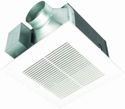
Saturday, April 13, 2013

Choices For Heating Your Conservatory

Conservatory heating is really a necessary expense if you want to apply your conservatory during the cold months several weeks or Fall/Spring on overcast days or perhaps in the nights. The are a number of ways to warmth your conservatory and we'll take a look at a number of them here, looking into the relative rewards and disadvantages of every method including purchase prices, installation costs and running costs where possible. Here is a review of a few of the techniques of heating your conservatory together with approximate costings around the assumption of the 10m2 area. Assumes 2kW heating requirement and average electricity tariff of 12p. Running price is when on and never annual average.

Conservatory Heating Method

Fan heater

Cost - £10 Running costs - 24p
Oil Filled Radiator

Cost - £30 Running cost - 24p
Electric panel heater

Cost - £150 Running Cost - 24p
Evening storage heater - economy 7

Cost - £175 Running Cost - 9p
Connect with existing home heating system

Cost - £250 Running Cost - 9p
Split unit ac system as heater

Cost - £500+ Running Cost - 24p
Air source electric + under tile heating

Cost - £2150 Running Cost - 6p
Good reasons to warmth your conservatory?

You may make use of your conservatory like a breakfast room by which situation it must be warm in morning throughout the year. Should you conservatory can be used during the day throughout Winter it may be beneficial to possess a heating solution that either includes a very constant temperature or could be capped up throughout your day if needed. Possibly you retain sub-tropical or tropical plants inside it that could not withstand the freezing temps we obtain during the cold months here. It mustn't drop below a particular temperature. Kinds of heater fall directly into 2 primary groups

Electric conservatory heating Pro's

No ventilation needed Rapidly adjust the temperature Simple to adjust Clean
Con's

Running costs could be high
Gas conservatory heating Pro's

Low running costs
Con's

Ventilation needed Several specific methods for heating your conservatory

Domestic heating system

You can simply connect a brand new radiator for an existing heating system. Seek advice from your conservatory supplier or local building officials to make certain this really is permitted. For those who have a competent boiler already this method have a really low running cost. It's a requirement the radiator you set within the conservatory features its own thermostatic control and could be switched off. For max warmth circulation it's recommended to set up the radiator close to the dwarf wall though this isn't always possible nor indeed convenient.

Pro's

Cheap to operate - believed 9p each hour for 2kW of heating presuming high quality boiler and warmth transfer system internally.
Con's

Go to Argos or whomever and purchase an admirer heater

Pro's

Cost ~ £10-20 for any 2kW unit Portable
Con's

Noisy Ventilation could be irritating High running costs ~ 24p each hour for 2kW of heating.
Electric panel heater

Buy and use a simple low profile electric panel heater.

Pro's

Simple to install- hook it up Fairly inexpensive ~ £150 Lots of warmth available Up to 3kW per unit Quick to warm up Slim line
Con's

Running costs could be high ~ 24p each hour for 2kW of heating.
Oil filled radiator

Forms of offered by 'most good retailers'

Pro's

Inexpensive ~ £30 for 2kW unit
Cons

Not slim line Heavy to maneuver High running costs ~ 24p each hour for 2kW of heating.

Evening storage heater

While not as style because they were in the past they're still available broadly and today they're a lot more slim line compared to huge brick filled blocks they was once.

Pro's

Can operate of economy 7 ~ 9p each hour for 2kW of heating throughout the evening. Fairly inexpensive ~ £175 for 2kW unit
Con's

Could be costly to set up Difficult to manage Costly to 'boost' ~ 24p each hour for 2kW of heating.
Tubular Heating

This really is generally utilized in outdoors rooms, sheds and green-houses in which the desire would be to avoid the room from going below zero that could damage plants, pipes along with other products.

Pro's

Frost protection kits available. Made to be employed in damper conditions e.g. glass house or garden storage shed. Splash proof if conservatory used for many plants that require watering. Cost ~ £20-40 including frost thermostat
Con's

Low energy only really functional for frost protection
Free-standing gas fire

A calor gas heater is definitely an example but an be either butane or gas based on design.

Pro's

No installation costs Portable Cost ~ £125
Con's

Could be bulky Heavy to maneuver Sometimes smell Cause condensation
Electric

Warmth pumps are available in two types air source and ground source. This defines where they extract the warmth from. Warmth pumps are generally used because the source for any under floor home heating because of the reduced temperature water they produce. Air source warmth pumps also employ systems having a fan around the interior warmth exchanger to blow heated air in. They operate while using refrigeration cycle. Within a fridge is cold and also the back warmth exchanger is warm. Inside a electric the outdoors world is cooled off and also the warmth is pumped in to the inside. The benefit is the fact that typically for each 1 unit of electricity 4 models of warmth could be introduced inside.

Pro's

May also be used like a cooling means Could be wall or floor mounted. Low running costs ~ 6p each hour for 2kW of heating presuming 4 to at least one warmth gain.
Con's

Generally costly
Ground source electric Pro's

Better suited to extract warmth in cold weather in the atmosphere than air source
Con's

Probably too costly for conservatory cooling unless of course considered included in a bigger alternation in heating system or perhaps in a brand new build construction.
Air source electric Pro's

Less costly as ground source ~ £1500
Con's

Still costly
Conservatory under floor heating

Pipes are run either beneath the tiles or inside the floor screed. These pipes have a working fluid that may be heated thus heating the ground surface.

Pro's

Comfortable method of heating an area Invisible Does not occupy any space Could be powered off heating, electric, electric or gas source Low running cost despite electric as usually find ambient temperature could be lower but still comfortable.
Con's

Installation cost ~ £350 for install in 10m2 Cost ~ £250-300 for 10m2 package under tile Cost ~ £200-250 for 10m2 package in screed
Ac

Whether portable unit with vent to outdoors world or perhaps a split system appropriately installed and attached to the wall. Ac models are often selected on their own cooling capacity instead of their heating abilities. Therefore running cost is challenging calculate.

Pro's

Clearly will work for cooling too
Con's

Noise Cost ~ £500+ for split system Cost ~ £250+ for portable system
Just how much heating will i need?

The quantity of heating needed is dependent on

Size conservatory Insulation qualities from the glass/frame - U value Needed temperature differential - temperature inside to outdoors To complicate things the form from the conservatory and climate conditions this type of wind speed will effect the warmth loss but they're not considered here.

Warmth loss is modelled while using following equation

Heating needed (w) equals U value * Area * temperature difference

Area may be the glass part of the conservatory plus 1/3rd from the part of the hooking up wall. It will get more difficult when the conservatory is built using different double glazed options (e.g. roof) or perhaps is tilted. So for any conservatory having a 10m2 floor area and a pair of.4m high walls and slightly sloping roof you might come with an section of 37.3m2.

Single double glazed includes a U worth of around 5 or even more. Old-style replacement windows is all about 3. More recent low-e films are nearer to 2 with triple glazed argon filled (read costly) models as little as .4!

Presuming you want to possess a minimum temperature of 18C during the day (with say an outdoors temperature of zero) we are able to then calculate the needed best situation heating requirement at approximately 2kW. With low-e glass it might be about 1.3kW.

Note: A dealer of conservatories or heat tank will have the ability to input more realistic figures but case ballpark. It enables us to check different techniques of heating the conservatory for cost on the very typical size conservatory.

It's obvious that a great way of heating your conservatory would be to stop any warmth inside the structure getting away to begin with. However, very high end glass (for example tripled glazed argon filled low-e variety) can be quite costly and based on your conservatory usage you might never recover an investment in reduced heating bills.

Conservatory Heating Conclusions

You will find a couple of techniques used in heating your conservatory. Often the lower upfront cost the greater the functional cost. Ultimately its a tough call regarding just how much to invest on well insulated glass and just how much to invest on efficient heating systems. Hopefully this introduction to techniques and costings has provided the information to create a better informed decision.